
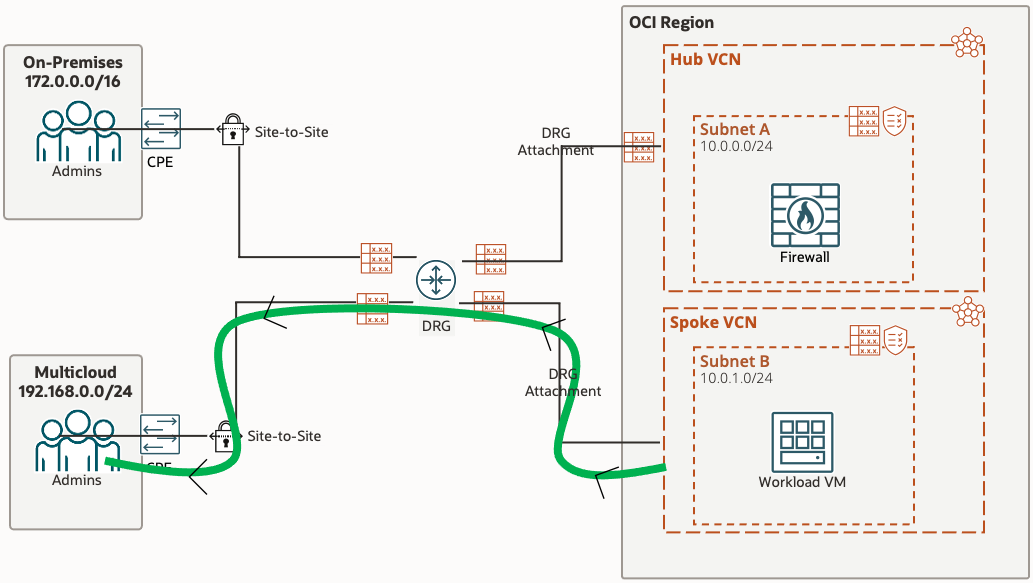
Advanced Networking - Using DRG to route certain traffic through centralized Network Firewall (and other traffic direct to Spoke) [Terraform]
![Advanced Networking - Using DRG to route certain traffic through centralized Network Firewall (and other traffic direct to Spoke) [Terraform]](/content/images/size/w2000/2024/02/hub-and-spoke-drg.png)
In this article you'll find the full terraform script to spin up & configure the end-2-end architecture, a long with a selective walkthrough of the main terraform code through snippets, finished off with a networking explanation pertaining to the main OCI components
We are effectively using the methodology explained in the Using a DRG to route traffic through a centralized network virtial appliance. The referenced documentation explains the entire setup, the concepts involved and the traffic flow & routing. Our architecture is a slight modification for a scenario requested by a customer, in which traffic from 1 destination follows the referenced flow but other traffic bypasses the centralized network firewall and is routed directly to the end target. The entire setup is done in Terraform. The terraform scripts also mimics customer connectivity (via IPSec tunnel) using Libreswan, all of which the terraform scripts configure with the help of Ansible, but more on that later.
 ShahvaizJanjua
All the code in this blog can be found here
We'll cover the following;
- Architecture
- OCI Networking Concepts
- Terraform scripts involved
- Terraform code walkthrough
- Traffic Flow & Route Table Explanation (Bonus)
Architecture
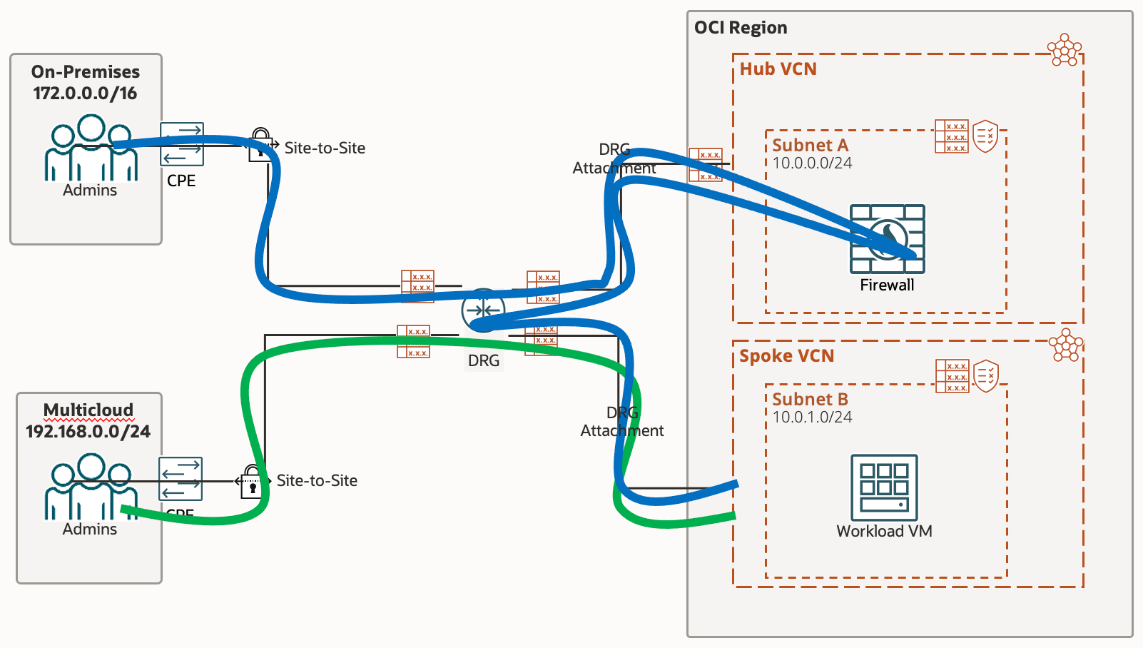
Our setup has the following components & requirements;
- Hub VCN, containing an OCI Network Firewall
- A Spoke VCN which has the customer OCI workload, represented through a single Compute Instance
- 2 separate IPSec tunnels, each connecting to a different site
- All traffic from Workload VM to 'On-Premise" site must pass through the firewall via the DRG and then be routed to the DRG and down the IPSec tunnel for 'On-Premises' and vice versa - represented with the blue highlight
- All traffic from Workload VM to 'Multicloud' site will go directly to the 'Multicloud' IPSec tunnels via the DRG, bypassing the Network Firewall - represented with the green highlight
- 'On-Premises' and 'Multicloud' sites are represented by the following setup;
VCN created for each site, containing 2 subnets. 1 Subnet for the CPE and 1 Subnet to represent customer workload/vm's
CPE is represented via Libreswan, a free IKE implementation for Linux, which is installed on a Compute Instance - Traffic Logging enablement for Network Firewall to confirm the required traffic is passing through the firewall
OCI Networking Concepts
Lets take a look at a couple of OCI Networking Concepts;
DRG Attachment;
Connects the Dynamic Routing Gateway to either a; Virtual Cloud Network, Virtual Circuit, IPSec or Remote Peering Connection. The DRG attachment allows the DRG to send traffic and receive traffic to & fro the given attached resource.
Every DRG attachment has a DRG Route Table associated with it. This DRG Route Tables Rules are used to route traffic incoming to the DRG from the other end of the attachment (e.g. the IPSec in an IPSec Attachment).
VCN attachments can have 2 Route Tables; 1 DRG Route Table for traffic incoming to the DRG from the VCN, 1 VCN Route Table for traffic incoming to the VCN from the DRG (this differs from normal use of VCN Route Tables which route traffic leaving the Subnet)
Dynamic Route Import Distribution
Before understanding Dynamic Route Import Distributions, it is important to note that a DRG Route Table contains both Static Routes and Dynamic Routes. Static Routes Rules are manually added by us; however a Static Route can only have a Virtual Cloud Network, Remote Peering Connection or Cross-Tenancy as its next hop. So in order to route traffic to IPSecs or Virtual Circuits we require to produce the rules dynamically, which is where Dynamic Route Import Distributions comes into play.
An Import Route Distribution is associated with a DRG Route Table. It contains a set of statements which are criteria's from which DRG attachments to use to populate the dynamic route rules in the DRG route table. When an DRG attachment matches the criteria, all routes associated with the attachments are dynamically imported into the DRG Route Table; for example for a Virtual Circuit all routes advertised using BGP will be imported into the DRG Route Table with the next hop as the DRG attachment (i.e. the Virtual Circuit). The match criteria can be;
- Match All
- Attachment Type - in which you specify the attachment type such as Virtual Circuit - results in all IPs advertised over BGP in ALL Virtual Circuits being dynamically added to the DRG Route Table
- Attachment - in which you specify an individual Attachment, such as a single Virtual Circuit - results in only the IPs advertised over BGP for that specific Virtual Circuit to be dynamically added to the DRG Route Table
Terraform Scripts
Before we dive into the code, lets take a very quick high level look at the scripts;
- Variables.tf - Holds all of our variables; Network CIDRs default values set, can be modified as desired
- Terraform.tfvars - To be populated, variables pertaining to terraform OCI authentication and keys
- Compartments.tf - Holds the OCI provider block and creation of compartment under root compartment
- Data.tf - Holds all Data Sources
- Networking.tf - Setups all networking elements except DRG & IPSec tunnels - i.e. VCNs, Subnets, VCN Route tables, Default Security List modification, Internet Gateway
- NetworkFirewall.tf - Creation of OCI Network Firewall Policy & OCI Network Firewall
- Logging.tf - Enable Traffic Logs to be collected from Network Firewall
- Compute.tf - Creation of OnPrem CPE/Librewan, OnPrem Workload VM, Multicloud CPE/Librewan, Multicloud Workload VM, Spoke (OCI Workload) VM
- DRG.tf - Creation of DRG, DRG Route Tables, DRG Route Table Import Distribution & DRG Attachments
- IPSec.tf - Creation of CPEs & IPSecs. Updating; IPSec Tunnels Interface IPs & IPSec Tunnel attachments DRG Route Table
- LibreswanSetup.tf - Ansible integration to execute ansible playbook to setup Libreswan configuration
- Ansible-vars.tf - Dynamically populate .yml file containing all of the values required by Libreswan config files
- /ansible/multicloud-libswan.yml & /ansible/onprem-libreswan.yml - Ansible scripts to; Install Libreswan, upload Libreswan config files, modify kernel parameters, start Libreswan, configure static routing
- /ansible/multicloud-libreswan.j2 & /andible/onprem-libreswan.j2 - Libreswan config file, populated from the file created dynamically by Ansible-vars.tf
- /ansible/multicloud-libreswan_secrets - IPSec tunnels shared secret, populated from the file created dynamically by Ansible-vars.tf
- vpn_vars not needed, add values to ansible-vars.tf, remove reference from .yml and delete
Terraform Code
Lets get into the Code;
Networking.tf
Creation of VCNs, Subnets, Internet Gateway and population of Route Tables and Security Lists are quite straightforward. Ideally we would utilise Network Security Groups, but for the purposes of this Customer Demonstration we simply used the default Security Lists and opened them up to the world.
resource "oci_core_default_security_list" "spoke_default_sl" {
    manage_default_resource_id = oci_core_vcn.spoke_vcn.default_security_list_id
    compartment_id = oci_identity_compartment.demo.id

   ingress_security_rules {
    protocol = "all"
    source = "0.0.0.0/0"
   }

    egress_security_rules {
    protocol = "all"
    destination = "0.0.0.0/0"
   }
}
You can modify the rules for the default security list by using the manage_default_resource_id. The default security list id is an attribute of a VCN resource, so we can obtain it directly from our VCN resource via oci_core_vcn.spoke_vcn.default_security_list_id
Default Route table follows the same premise;
resource "oci_core_default_route_table" "multicloud_default_route_table" {
    manage_default_resource_id = oci_core_vcn.multicloud_vcn.default_route_table_id
    display_name = "Default Route Table"

    route_rules {
        network_entity_id = oci_core_internet_gateway.multicloud_igw.id
        destination = "0.0.0.0/0"
        destination_type = "CIDR_BLOCK"
    }
}
Compute.tf
Compute Resource is also quite straight forward, the only interesting part is obtaining the Image ID which needs to be given in the source_details attribute of Compute resource
  source_details {
    source_type = "image"
    source_id   = data.oci_core_images.os.images[0].id
  }
As you can see the Image ID is obtained from a Data Source, which gives us a list of images and we simply select the first element in the list. So lets take a look at the data source that this references
data "oci_core_images" "os" {
  compartment_id           = oci_identity_compartment.demo.id
  operating_system = "Oracle Linux"
  operating_system_version = "8"

  shape                    = "VM.Standard.E4.Flex"
  sort_by                  = "TIMECREATED"
  sort_order               = "DESC"
}
We use the oci_core_images Data Source and specify the shape of our Compute to ensure we only get images compatible with our shape. We also want Oracle Linux 8 so we populate operating system details and are ordering by the newest created image.
We need to specify Public Key for SSH
  metadata = {
    ssh_authorized_keys = file(var.public_key_path)
  }
We do this by referencing the variable that holds the path to our Public Key file and telling it that it is a file.
DRG.tf
The DRG setup is mostly also straight forward, we require to do the following;
- Create Dynamic Routing Gateway
- Create DRG Route Tables
- Create DRG Route Table Rules (to populate DRG Route Tables)
- Create Import Route Distribution
- Create Import Route Distribution Statements (to populate Import Route Distribution)
- Create DRG VCN attachments
resource "oci_core_drg_route_table_route_rule" "drg_multicloud_ipsec_rt_rule" {
    drg_route_table_id = oci_core_drg_route_table.drg_multicloud_ipsec_rt.id
    destination = oci_core_vcn.spoke_vcn.cidr_block
    destination_type = "CIDR_BLOCK"
    next_hop_drg_attachment_id = oci_core_drg_attachment.spoke_drg_attachment.id
}
For the rule, we specify the DRG Route Table ID for which the Rule is for, and then the Destination Type, followed by the Destination address and what the next hop is. Lets take a look at populating our Import Route Distribution; as with DRG Route Tables, you create the Import Route Distribution via a resource and then populate it via a separate Import Route Distribution Statement resource
resource "oci_core_drg_route_distribution_statement" "drg_hub_route_distribution_statement" {
    drg_route_distribution_id = oci_core_drg_route_distribution.drg_hub_route_distribution.id
    action = "ACCEPT"

    match_criteria {
        match_type = "DRG_ATTACHMENT_TYPE"

        attachment_type = "IPSEC_TUNNEL"
    }
    priority = 1
}
We cannot have overlapping priorities so it is important that each statement has a unique priority number. Here we are specifying DRG_ATTACHMENT_TYPE meaning all the advertised (or static) addresses of that attachment type will be imported, irrespective of how many of those attachments there are (i.e. this will import route rules for ALL IPSec Tunnels). To specify it for only a single tunnel we can use DRG_ATTACHMENT_ID and specify the actual ID, as below;
resource "oci_core_drg_route_distribution_statement" "drg_spoke_route_distribution_statement1" {
    drg_route_distribution_id = oci_core_drg_route_distribution.drg_spoke_route_distribution.id
    action = "ACCEPT"

    match_criteria {
        match_type = "DRG_ATTACHMENT_ID"

        attachment_type = "IPSEC_TUNNEL"
        drg_attachment_id = oci_core_drg_attachment_management.multicloud_ipsec_attachment_tunnel_a.id
    }
    priority = 1
}Creating a DRG Attachment in order to attach DRG to VCN is straightforward
resource "oci_core_drg_attachment" "hub_drg_attachment" {
  drg_id             = oci_core_drg.drg.id
  display_name       = "Hub-VCN-Attachment"
  drg_route_table_id = oci_core_drg_route_table.drg_hub_rt.id

  network_details {
    id             = oci_core_vcn.hub_vcn.id
    type           = "VCN"
    route_table_id = oci_core_route_table.hub_vcn_ingress_rt.id
  }
}
IPSec.tf
The creation of CPE & IPSec Connection itself is straight forward
resource "oci_core_ipsec" "onprem_ipsec_connection" {
  compartment_id = oci_identity_compartment.demo.id
  cpe_id         = oci_core_cpe.onprem_cpe.id
  drg_id         = oci_core_drg.drg.id
  static_routes  = [oci_core_vcn.onprem_vcn.cidr_block]

  cpe_local_identifier      = oci_core_instance.onprem_libreswan.public_ip
  cpe_local_identifier_type = "IP_ADDRESS"
  display_name = "OnPrem-IPSec"
}
We're using Static Routing for the IPSec connection, as opposed to BGP dynamic routing or policy-based routing. Hence we populate static_routes for each IPSec connection, the value simply being our OnPremise IP address range
In order to update the default tunnel name and specify the tunnel interface IPs, we require to use the oci_core_ipsec_connection_tunnel_management resource
resource "oci_core_ipsec_connection_tunnel_management" "onprem_ipsec_tunnel_management_a" {
  ipsec_id  = oci_core_ipsec.onprem_ipsec_connection.id
  tunnel_id = data.oci_core_ipsec_connection_tunnels.onprem_ipsec_tunnels.ip_sec_connection_tunnels[0].id
  depends_on = [data.oci_core_ipsec_connections.onprem_ipsec_connections]

   bgp_session_info {
        customer_interface_ip = "10.10.10.1/30"
        oracle_interface_ip = "10.10.10.2/30"
    }

  display_name  = "OnPrem-IPSec-tunnel-a"
  routing       = "STATIC"
  ike_version   = "V1"
}
We require a separate resource for each of the 2 tunnels, hence why this resource is called onprem_ipsec_tunnel_management_a, as we have b for the second tunnel
We also need to attach the DRG Route Table to the IPSec DRG attachment
resource "oci_core_drg_attachment_management" "onprem_ipsec_attachment_tunnel_a" {
  attachment_type = "IPSEC_TUNNEL"
  compartment_id = oci_identity_compartment.demo.id
  network_id = data.oci_core_ipsec_connection_tunnels.onprem_ipsec_tunnels.ip_sec_connection_tunnels.0.id
  drg_id = oci_core_drg.drg.id
  display_name = "drg-ipsec-onprem-attachment-tunnel-a"
  drg_route_table_id = oci_core_drg_route_table.drg_onprem_ipsec_rt.id
}
This needs to be done for each tunnel
NetworkFirewall.tf & Logging.tf
In order to create a Network Firewall, we first require to create a Network Firewall Policy
resource "oci_network_firewall_network_firewall_policy" "network_firewall_policy" {
    compartment_id = oci_identity_compartment.demo.id
    display_name = "Demo-Network-Firewall-Policy"
    security_rules {
        action = "ALLOW"
        condition {}
        name = "Allow-All-Traffic"
    }
}
Our policy is very straight forward, it has a Security Rule of Allow with no condition; i.e. unconditionally allow all traffic.
resource "oci_network_firewall_network_firewall" "network_firewall" {
    compartment_id = oci_identity_compartment.demo.id
    network_firewall_policy_id = oci_network_firewall_network_firewall_policy.network_firewall_policy.id
    subnet_id = oci_core_subnet.hub_sub.id
    display_name = "Demo-Network-Firewall"
}
We can then create our Network Firewall and pass it our Network Firewall Policy ID
We want to enable Traffic Logging for our Network Firewall so we can view the traffic flowing through our Network Firewall. First we must create a Log Group which will contain our Traffic Log
resource "oci_logging_log_group" "log_group" {
    compartment_id = oci_identity_compartment.demo.id
    display_name = "DemoLoggingGroup"
}
Now we can create and enable our Traffic logging
resource "oci_logging_log" "NFW_Log" {
    display_name = "Demo_NetworkFirewall_Log"
    log_group_id = oci_logging_log_group.log_group.id
    log_type = "SERVICE"
    configuration {
        source {
            category = "trafficlog"
            resource = oci_network_firewall_network_firewall.network_firewall.id
            service = "ocinetworkfirewall"
            source_type = "OCISERVICE"
        }
        compartment_id = oci_identity_compartment.demo.id
    }
    is_enabled = true
    retention_duration = 90
}
On-Premise & MultiCloud Setup
The On-Premise and MultiCloud sites have the same architecture, which is the one shown below.
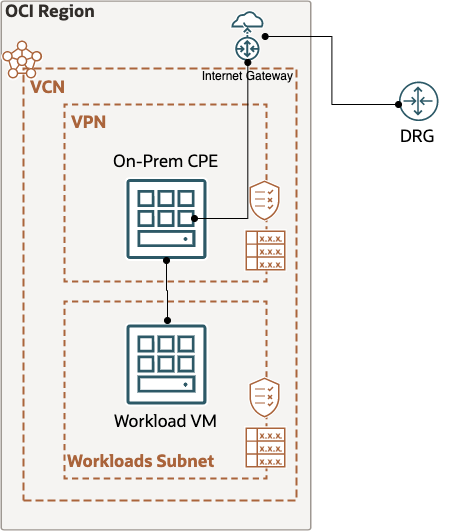
The routing is straight forward, the route table for On-Prem CPE/VPN subnet has all traffic going to Internet Gateway (traffic destined for Workload VM will automatically be routed there, no explicit firewall rules are required). The route table for Workload VM however will force all traffic destined to the OCI Site (Spoke VCN) to the CPE/VPN, which in turn will send the traffic through the DRG/Site-to-Site tunnels via the Internet Gateway.
For the VPN/CPE Subnets route table, we simply use the default route table;
resource "oci_core_default_route_table" "onprem_default_route_table" {
    manage_default_resource_id = oci_core_vcn.onprem_vcn.default_route_table_id
    display_name = "Default Route Table"
    route_rules {
        network_entity_id = oci_core_internet_gateway.onprem_igw.id
        destination = "0.0.0.0/0"
        destination_type = "CIDR_BLOCK"
    }
}
For the Workload VMs Subnet we create a new route table and specify a rule to ensure all traffic destined for the Spoke VCN is sent to the CPE/VPN VM
resource "oci_core_route_table" "onprem_wl_rt" {
    compartment_id = oci_identity_compartment.demo.id
    vcn_id = oci_core_vcn.onprem_vcn.id
    display_name = "OnPrem_Priv_RT"
   route_rules {
        network_entity_id = data.oci_core_private_ips.onprem_libreswan_private_ip.private_ips[0].id
        destination = oci_core_vcn.spoke_vcn.cidr_block
        destination_type = "CIDR_BLOCK"
    }
    route_rules {
        network_entity_id = oci_core_internet_gateway.onprem_igw.id
        destination = "0.0.0.0/0"
        destination_type = "CIDR_BLOCK"
    }
}
Now we move onto configuring the VPN/CPE/Libreswan via Ansible
All of the VM and Libreswan configuration is done via Ansible. How do we execute ansible from terraform ? Quite simple, we use the local-exec provisioner to execute the ansible script on the CPE/VPN VM from our terraform host, by giving it the SSH details and the ansible script that needs to be executed. However if we simply do local-exec it will try and execute this before the VM is ready, so we use remote-exec to first ensure we can establish an SSH session
resource "null_resource" "onprem-libreswan-config" {
  depends_on = [local_file.ansible-libreswan-vars]
  provisioner "remote-exec" {
    inline = ["echo About to run Ansible on LIBRESWAN and waiting!"]
    connection {
      host        = "${oci_core_instance.onprem_libreswan.public_ip}"
      type        = "ssh"
      user        = "opc"
      private_key = file(var.private_key_path)
    }
  }
  provisioner "local-exec" {
    command = "sleep 30; ANSIBLE_HOST_KEY_CHECKING=False ansible-playbook -u opc -i '${oci_core_instance.onprem_libreswan.public_ip},' --private-key '${var.private_key_path}' ./ansible/onprem-libreswan.yml"
  }
}
From the above we can gather that the ansible script to be executed is onprem-libreswan.yml and resides in a folder called ansible. Let's take a look at this script one bit at a time
- hosts: all
  become: yes
  vars_files:
    - ./vpn_vars/onprem-tunnel.yml
    - ../ansible-libreswan-vars.yml

  tasks:
We specify the host this is being executed on, any files containing required variables, followed by the series of tasks to be performed on the host
 - name: install libreswan
    yum:
      name: libreswan
      state: installed
The first task is straight forward, install Libreswan
  - name: write the vpn config file
    template: src=onprem-libreswan.j2 dest=/etc/ipsec.d/oci-vpn-tunnels.conf
    become: yes

  - name: write the vpn secrets file
    template: src=onprem_libreswan_secrets.j2 dest=/etc/ipsec.d/oci-vpn-secrets.secrets
    become: true
Next we copy over the required configuration files for Libreswan, we'll take a look at how we dynamically create this configuration very soon, but first the remaining ansible tasks
- name: Enable Ibr_netfilter IPv4
    copy:
      dest: /etc/sysctl.conf
      content: |
        net.ipv4.ip_forward = 1
        net.ipv4.conf.default.rp_filter = 0
        net.ipv4.conf.all.rp_filter = 0
        net.ipv4.conf.all.send_redirects = 0
        net.ipv4.conf.default.send_redirects = 0
        net.ipv4.icmp_ignore_bogus_error_responses = 1
        net.ipv4.conf.default.log_martians = 0
        net.ipv4.conf.all.log_martians = 0
        net.ipv4.conf.default.accept_source_route = 0
        net.ipv6.conf.default.accept_source_route = 0
        net.ipv4.conf.all.accept_redirects = 0
        net.ipv6.conf.all.accept_redirects = 0
        net.ipv4.conf.default.accept_redirects = 0
        net.ipv6.conf.default.accept_redirects = 0

  - name: Apply Persistent IPv4 Forwarding
    shell: sudo sysctl -p

  - name: Disable Selinux
    shell: sudo setenforce 0

  - name: Disable Firewalld
    shell: sudo systemctl stop firewalld

  - name: ensure ipsec is running
    service: name=ipsec state=started
    become: yes

  - name: Apply Persistent IPSEC connection
    shell: systemctl enable ipsec.service
    become: yes
Next we enable IP forwarding, as well as modifying some kerner parameters.
We disable Selinux, firewalld and start libreswan/ipsec
  - name: Configure Hub Static Route
    shell: sudo ip route add {{ oci_hub_cidr }} nexthop dev vti1 nexthop dev vti2

  - name: Configure Spoke Static Route
    shell: sudo ip route add {{ oci_spoke_cidr }} nexthop dev vti1 nexthop dev vti2
We then add static routing such that all traffic destined to OCI (Hub VCN & Spoke VCN) passes through the Virtual Tunnel Interface's
Libreswan has 2 main files, 1 is for the IPSec configuration and the 2nd holds the Shared Secret for the Site-to-Site VPN Tunnels. The ansible yml code we saw previously is copying these 2 files from your terraform host server to the CPE/VPN VMs. Let's take a look at the 2 files;
conn {{ onprem_conn_name_tunnel1 }}
     authby=secret
     pfs=yes
     left={{ onprem_cpe_local_ip }}
     leftid={{ onprem_cpe_public_ip }}
     leftsubnet=0.0.0.0/0
     leftnexthop=%defaultroute
     right={{ onprem_oci_tunnel1_headend }}
     rightid={{ onprem_oci_tunnel1_headend }}
     rightsubnet=0.0.0.0/0
     mark=5/0xffffffff # Needs to be unique across all tunnels
     vti-interface=vti1
     vti-routing=no
     leftvti={{ onprem_tunnel1_leftvti }}
     ikev2=no # To use IKEv2, change to ikev2=insist
     ike=aes_cbc256-sha2_384;modp1536
     phase2alg=aes_gcm256;modp1536
     encapsulation=yes
     ikelifetime=28800s
     salifetime=3600s
     auto=start
conn {{ onprem_conn_name_tunnel2 }}
     authby=secret
     pfs=yes
     left={{ onprem_cpe_local_ip }}
     leftid={{ onprem_cpe_public_ip }}
     leftsubnet=0.0.0.0/0
     leftnexthop=%defaultroute
     right={{ onprem_oci_tunnel2_headend }}
     rightid={{ onprem_oci_tunnel2_headend }}
     rightsubnet=0.0.0.0/0
     mark=6/0xffffffff # Needs to be unique across all tunnels
     vti-interface=vti2
     vti-routing=no
     leftvti={{ onprem_tunnel2_leftvti }}
     ikev2=no # To use IKEv2, change to ikev2=insist
     ike=aes_cbc256-sha2_384;modp1536
     phase2alg=aes_gcm256;modp1536
     encapsulation=yes
     ikelifetime=28800s
     salifetime=3600s
     auto=start
This is the basic configuration file for Libreswan. Here we are setting up 2 IPSec tunnels, connecting to 2 Public IPs which connect to a single DRG.
The source secrets file which holds the Shared Secret for each tunnel looks like this
{{ onprem_cpe_public_ip }} {{ onprem_oci_tunnel1_headend }} : PSK "{{ onprem_shared_secret_psk1 }}"
{{ onprem_cpe_public_ip }} {{ onprem_oci_tunnel2_headend }} : PSK "{{ onprem_shared_secret_psk2 }}"
As you can see there are variables for the actual values; this allows us to dynamically create the configuration based on our specific implementation as whenever you run the terraform and provision new resources we'll have a new set of Public IPs, Private IPs, Shared Secret Keys, IPSec Headend IPs etc. So how do we define these variables ?
ansible-vars.tf
We dynamically create a new file containing our variable names and their values. The values are extracted from either the terraform resources we create or the data sources that we define
resource "local_file" "ansible-libreswan-vars" {
  content = <<-DOC
    # Ansible vars_file containing variable values from Terraform.
    # Generated by Terraform mgmt configuration.
    onprem_cpe_local_ip: ${oci_core_instance.onprem_libreswan.private_ip}
    onprem_cpe_public_ip: ${oci_core_instance.onprem_libreswan.public_ip}
    onprem_oci_tunnel1_headend: ${data.oci_core_ipsec_connection_tunnels.onprem_ipsec_tunnels.ip_sec_connection_tunnels[0].vpn_ip}
    onprem_oci_tunnel2_headend: ${data.oci_core_ipsec_connection_tunnels.onprem_ipsec_tunnels.ip_sec_connection_tunnels[1].vpn_ip}
    onprem_shared_secret_psk1: ${data.oci_core_ipsec_config.onprem_ipsec_config.tunnels[0].shared_secret}
    onprem_shared_secret_psk2: ${data.oci_core_ipsec_config.onprem_ipsec_config.tunnels[1].shared_secret}
    multicloud_cpe_local_ip: ${oci_core_instance.multicloud_libreswan.private_ip}
    multicloud_cpe_public_ip: ${oci_core_instance.multicloud_libreswan.public_ip}
    multicloud_oci_tunnel1_headend: ${data.oci_core_ipsec_connection_tunnels.multicloud_ipsec_tunnels.ip_sec_connection_tunnels[0].vpn_ip}
    multicloud_oci_tunnel2_headend: ${data.oci_core_ipsec_connection_tunnels.multicloud_ipsec_tunnels.ip_sec_connection_tunnels[1].vpn_ip}
    multicloud_shared_secret_psk1: ${data.oci_core_ipsec_config.multicloud_ipsec_config.tunnels[0].shared_secret}
    multicloud_shared_secret_psk2: ${data.oci_core_ipsec_config.multicloud_ipsec_config.tunnels[1].shared_secret}
    oci_hub_cidr: ${oci_core_vcn.hub_vcn.cidr_block}
    oci_spoke_cidr: ${oci_core_vcn.spoke_vcn.cidr_block}
    DOC
  filename = "./ansible-libreswan-vars.yml"
We also have another file which contains the tunnels inside IPs a long with some other required information (FYI, we could add these variables to our script above and then have a single file)
---
#Name for the VPN Connetion
onprem_conn_name_tunnel1: oci-tunnel1
onprem_conn_name_tunnel2: oci-tunnel2

#Connection settings
onprem_tunnel1_cidr: "10.10.10.1/30"
onprem_tunnel2_cidr: "10.10.10.5/30"
onprem_left: "{{ onprem_cpe_local_ip }}"
onprem_tunnel1_right: "{{ onprem_oci_tunnel1_headend }}"
onprem_tunnel2_right: "{{ onprem_oci_tunnel2_headend }}"
onprem_vti1: "vti1"
onprem_vti2: "vti2"
onprem_oci_vcn_cidr: "{{ onprem_oci_vcn_cidr }}"
onprem_tunnel1_leftvti: "10.10.10.1/30"
onprem_tunnel2_leftvti: "10.10.10.5/30"
#PSK to be used.
onprem_vpn_psk1: "{{ onprem_shared_secret_psk1 }}"
onprem_vpn_psk2: "{{ onprem_shared_secret_psk2 }}"
Traffic Flow
With all of that covered, let's now take a look at the actual traffic flow by looking at each hope, the route table involved and the route rule for our traffic.
We'll look at the perspective of traffic coming from our Workload VM and going to our Site-to-Site VPNs.
To On-Premise (via Network Firewall)
On-Premise Network has a CIDR of 172.0.0.0/16
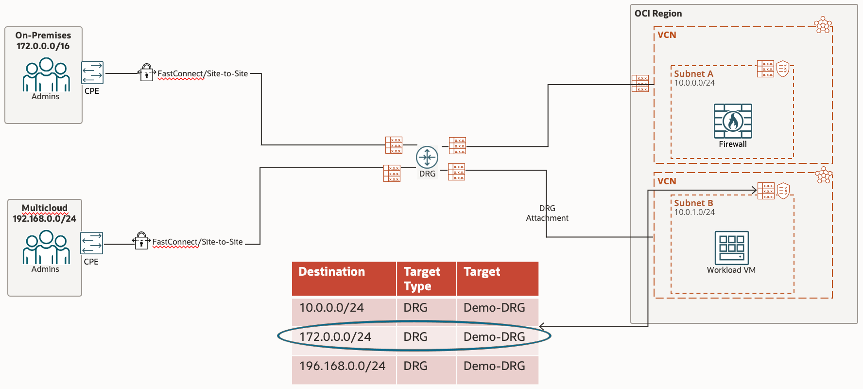
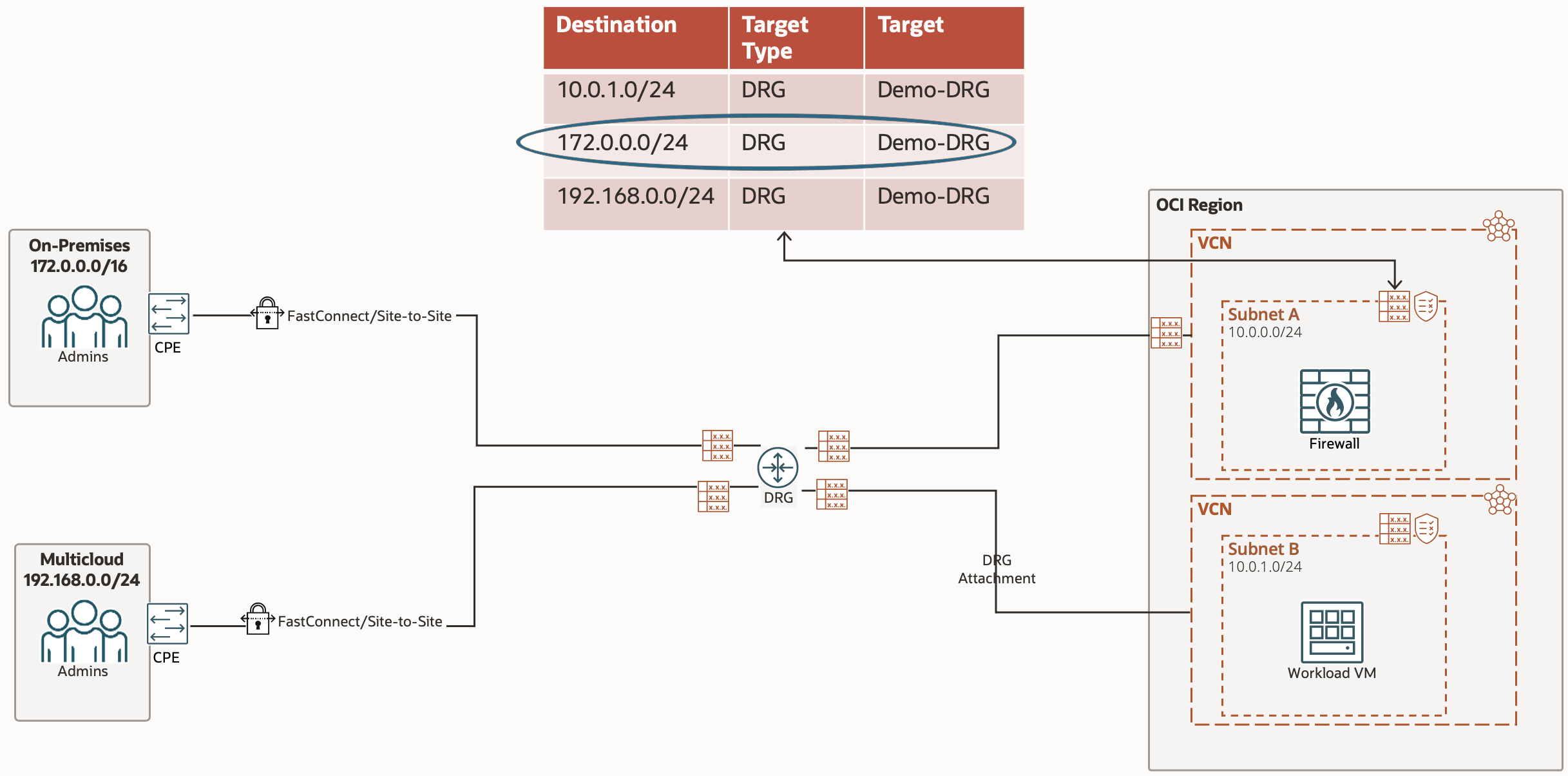
When trying to access On-Premise Site from the Workload VM, the route table in play first is the VCN Route Table associated with the subnet. In here we specify what traffic we want to go where; in this case we want the On-Premise CIDR (Destination) to go to the Demo-DRG, which is the next hop
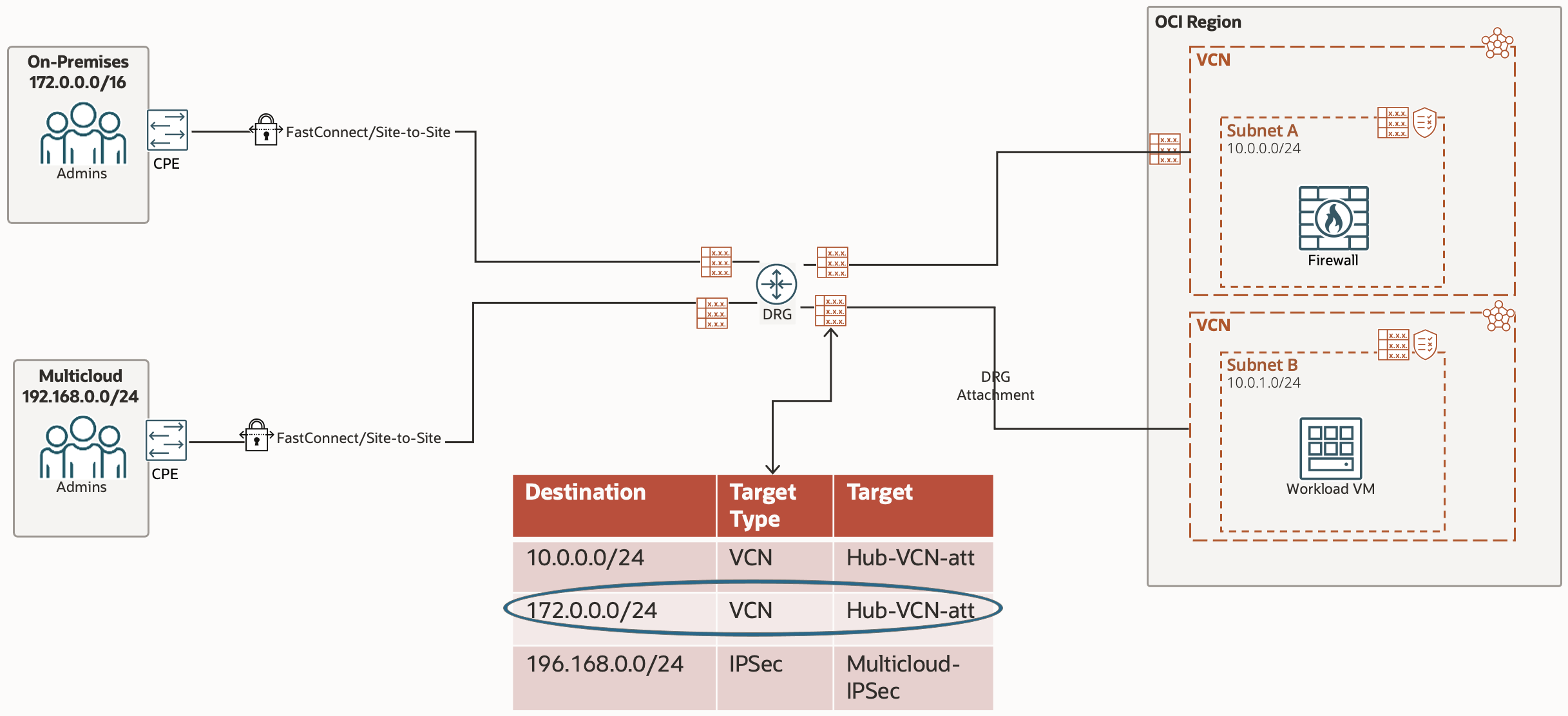
Now that the traffic is being passed to the DRG, we need to instruct the DRG where to pass the traffic to. The Route Table in play here is the DRG Route Table associated with this specific DRG Attachment.
The next hop in this route tables rule is the Hub VCN which is accessed via a DRG Attachment, which is why the Target Type is VCN and the Target is the Hub VCN DRG Attachment

The traffic is now being passed to the Hub VCN via the DRG Attachment. The Route Table in play is the VCN Route Table associated with the DRG Attachment connecting the Hub VCN and DRG. The Route Rule for our traffic is to the Private IP of the Network Firewall.
The traffic has passed through the Network Firewall, which has hopefully allowed the traffic through, so the Route Table in play now is the VCN Route Table associated with the subnet (in our case, the VCNs default route table). The Route Rule for our traffic sends the traffic to the DRG.
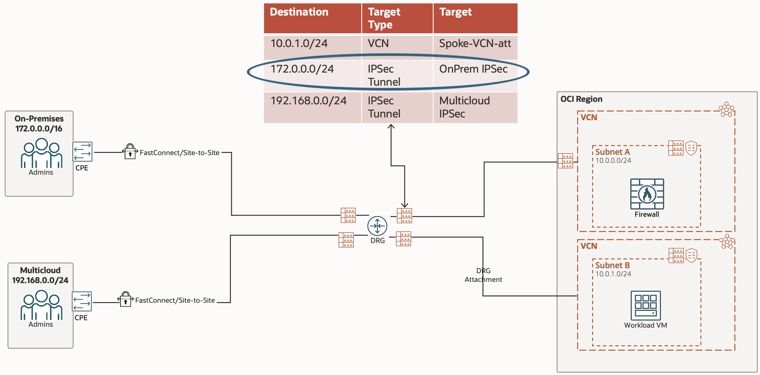
Now that the traffic is being sent to the DRG from the VCN, the Route Table in play is now the DRG Route Table associated with the DRG Attachment which connects the Hub VCN to the DRG.
The Route Rule targeting our traffic sends the traffic to the On-Premise IPSec, which will reach the On-Premise CPE. This Route Rule cannot be created manually (statically), instead it is done dynamically by using the Import Route Distribution associated with the DRG Route Table.
This has been explained in the Dynamic Route Import Distribution section
To Multicloud (bypassing Network Firewall)
The traffic to Multicloud Site follows a much simpler path!
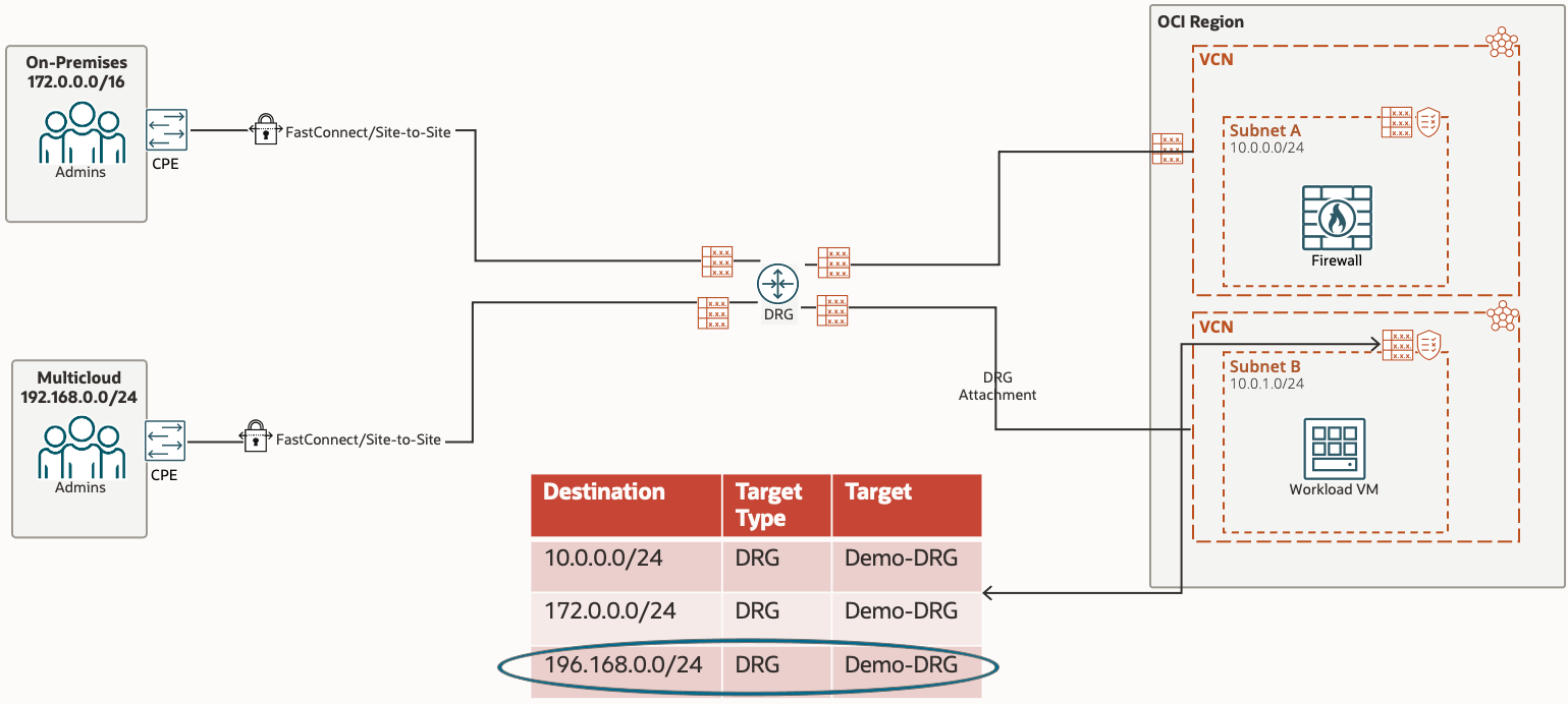
Traffic from our Workload VM in the Spoke VCN, to the Multicloud site, is given its first hop by the VCN Route Table associated with our subnet (in our case, the VCN default route table). The route rule tells all traffic destined for Multicloud to be sent to the DRG.
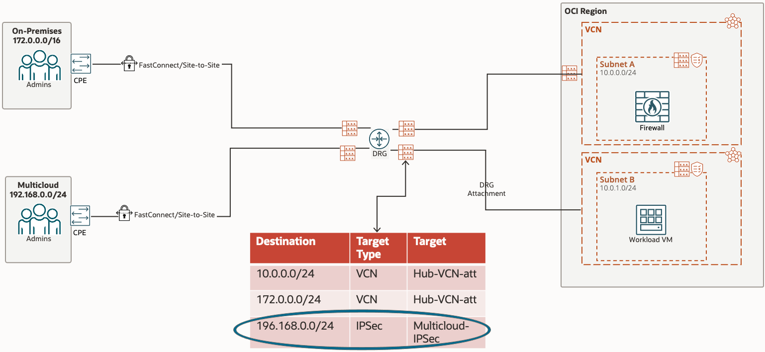
Once the traffic hits the DRG, the Route Table in play is the DRG Route Table associated with the DRG Attachment which connects the Spoke VCN to the DRG.
The route rule in this table tells the traffic that the next hop is the IPSec tunnel. As mentioned previously, this particular rule for IPSec is dynamically populated using the Import Route Distribution.